
June 23, 2026
How to Calculate the Load Capacity of a Hex Expansion Bolt
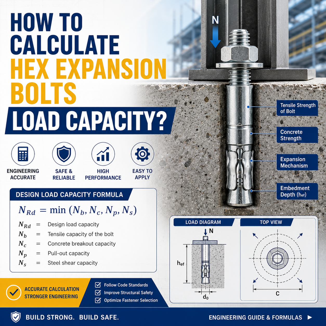
A structural engineer once showed me a bracket that had pulled clean out of a concrete ceiling. The hex expansion bolts were still intact. The concrete around them was not. The bolts had been specified by diameter alone—“use M12” was the instruction—without anyone calculating whether the concrete could actually hold them. The bracket came down under less than half the load it was supposed to carry.
Hex expansion bolts work by expanding a sleeve or wedge against the wall of a pre-drilled hole. When the bolt is tightened, the expansion mechanism presses outward, generating friction that locks the bolt into the base material. The load capacity is determined not by the bolt itself, but by the weakest link in a chain of four possible failure modes. The calculation process is about finding that weakest link and establishing a safe working load from it.
The Three Numbers You Need Before Calculation
Before any equation can be applied, three variables must be defined. First, the base material—concrete, solid brick, or natural stone—and its compressive strength. The manufacturer’s load tables typically reference cracked and uncracked concrete with a specified compressive strength, usually C20/25 (20 MPa cylinder strength). Second, the bolt diameter and embedment depth. The embedment depth is the distance from the concrete surface to the deepest point of the expansion mechanism. Third, the load direction—tension (pull-out), shear (perpendicular to the bolt axis), or combined loading.
The Four Failure Modes and Their Calculations
When a hex expansion bolt is loaded in tension, it can fail in four ways. The actual load capacity is the lowest of the four calculated values.
Pull-out failure occurs when the expansion mechanism is pulled out of the concrete, leaving the concrete around the hole largely intact. This happens when the embedment depth is insufficient or the concrete strength is low. The resistance is calculated as: N = τ × π × d × h, where τ is the bond stress between the expansion sleeve and the concrete, d is the hole diameter, and h is the effective embedment depth. For uncracked concrete of class C20/25, bond stress is typically 2.5–3.5 MPa for standard expansion bolts, rising to 4.0–5.5 MPa for high-performance anchors.
Concrete cone failure is the most common failure mode in properly installed expansion bolts. The concrete around the bolt fractures in a cone shape that extends outward from the expansion point to the concrete surface. The characteristic resistance of a single anchor in cracked concrete is calculated as: N_Rk,c = k1 × √f_ck × h_ef^1.5. k1 is a factor that depends on the anchor type and whether the concrete is cracked or uncracked. For cracked concrete, k1 = 7.7 for standard expansion bolts and 11.0 for torque-controlled expansion anchors. f_ck is the characteristic compressive cylinder strength in MPa. h_ef is the effective embedment depth in mm.
For an M12 torque-controlled expansion bolt embedded 70 mm in C20/25 cracked concrete, the calculation is: N_Rk,c = 11.0 × √20 × 70^1.5. √20 is approximately 4.47, and 70^1.5 is approximately 586. The product is 11.0 × 4.47 × 586 = 28,812 N, or 28.8 kN. This is the characteristic resistance. To obtain the design resistance, divide by the partial safety factor γ_Mc, typically 1.5 for concrete cone failure under the relevant design standard, and multiply by any applicable reduction factors.
Steel failure occurs when the bolt itself fractures under tension. This is rarely the governing failure mode because the steel in a hex expansion bolt is typically high-strength carbon steel with a tensile strength of 800 MPa or higher. The characteristic steel resistance is: N_Rk,s = A_s × f_uk, where A_s is the tensile stress area and f_uk is the characteristic ultimate tensile strength. For carbon steel anchors with f_uk of 800 MPa, the governing standard is ETAG 001 Annex C.
Splitting failure happens when the bolt is too close to an edge or when the spacing between bolts is insufficient. The concrete cracks through the line of least resistance. Edge distances of at least 1.5 times the embedment depth and bolt spacing of at least 3.0 times the embedment depth are the standard recommendations. For critical applications, these minimums should be verified against the anchor manufacturer‘s ETA (European Technical Assessment) document.
For an M12 expansion bolt in cracked C20/25 concrete with 70 mm embedment, the concrete cone capacity of roughly 28.8 kN characteristic translates to about 19.2 kN design resistance after applying the partial safety factor of 1.5. This is the load the bolt can reliably carry in tension. A working load limit for a single anchor would further apply a global safety factor, typically 3.0 to 4.0 for overhead or safety-critical applications, bringing the safe working load per bolt to approximately 4.8–6.4 kN, or roughly 480–650 kg.
Allowable Load: A Practical Comparison
The table below compares approximate allowable tensile loads for common hex expansion bolt sizes in cracked C20/25 concrete with standard embedment depths. These values are indicative and assume single anchors without edge or spacing influence. Always verify against the manufacturer’s ETA.
Bolt Size | Embedment Depth (mm) | Design Tensile Resistance (kN) | Approximate Safe Working Load (kg) |
M8 | 55 | 8.5–10.5 | 215–270 |
M10 | 60 | 13.0–16.5 | 330–420 |
M12 | 70 | 16.5–22.0 | 420–560 |
M16 | 85 | 26.0–34.0 | 660–870 |
M20 | 100 | 38.0–50.0 | 970–1,275 |
Allowable loads are given as the safe working load with a global factor of approximately 3.0–4.0.
FAQ
Q: Can I use hex expansion bolts in hollow brick?
A: No. Expansion bolts rely on the expansion mechanism pressing against the wall of a solid hole. In hollow brick, there is insufficient material for the expansion forces to develop. Use chemical anchors or through-bolts designed for hollow base materials.
Q: What is the minimum edge distance for hex expansion bolts?
A: The standard recommendation is a minimum edge distance of 1.5 times the effective embedment depth. For an M12 bolt with 70 mm embedment, that is approximately 105 mm. Closer edge distances require reduced loads per the manufacturer’s ETA.
Q: How does cracked concrete affect load capacity?
A: Cracked concrete reduces the concrete cone capacity. The k1 factor drops from 11.0 for uncracked concrete to 7.7 for cracked concrete in the case of standard expansion bolts. Always assume cracked concrete for structural design unless the concrete is verified to remain uncracked under all service loads throughout the service life of the anchorage.
Q: Can I reuse a hex expansion bolt after removal?
A: No. Once an expansion bolt has been set and removed, the expansion mechanism has been deformed and will not expand reliably a second time. Always install a new bolt in a new hole.
Summary
The load capacity of a hex expansion bolt is governed by the concrete it sits in, not the bolt itself. The calculation path runs from concrete cone capacity through steel strength to edge and spacing effects, and the lowest of these values defines what the bolt can safely carry. For specification purposes, never rely on bolt diameter alone. Specify the embedment depth, the concrete strength class, and the required edge distances. A bolt that is correctly specified and installed will carry its design load. A bolt specified by guess will eventually demonstrate which failure mode governs, and the demonstration will be expensive.